
Solar PV Layout Design: A Step-by-Step Guide for Utility-Scale Projects


The Importance of Optimized Layouts in Large-Scale Solar
A well-executed solar site design determines far more than where PV modules are placed. It maximizes the electricity generated, minimizes land use, reduces grading and cabling needs, and ensures that the PV system can be built efficiently and safely.
In this article, we outline each phase of the solar PV layout design workflow, and demonstrate how tools such as our award-winning PVFARM platform provide engineering-grade intelligence early in development; helping project teams fine-tune decisions, understand constraints faster, and align upstream engineering with downstream project execution.
Solar Site Design Fundamentals
Solar site design is the discipline of planning how PV modules, mounting structures, electrical equipment and supporting infrastructure will be arranged across a site to maximize performance, meet regulatory requirements, and ensure constructability.
Key Objectives of Solar PV Layout Design:
- Maximizing energy production by optimizing orientation, tilt, row spacing, and shading conditions
- Reducing costs across grading, cabling, trenching, roads, and structural works
- Optimizing land use while ensuring safe operations and maintenance access
- Ensuring constructability, especially across challenging topography
- Meeting regulatory, grid, and environmental requirements
- Aligning technical parameters with project financial and operational goals
A robust solar site design process evaluates all these elements before any PV modules are positioned within the site layout.
Step 1: Pre-Design Site Assessment
The foundation of effective solar PV layout design is accurate, high-resolution site data. This step ensures the solar PV system is being designed for actual site conditions, not assumptions.
Site Data Collection
A thorough pre-design assessment includes gathering the following data:
- Topographic Data: LiDAR, DEM, survey-grade contours
- Solar Resource Data: Long-term GHI/DNI datasets, albedo assumptions
- Geotechnical Data: Soil borings, slope stability, frost depth
- Environmental Data: Wetlands, protected habitats, drainage paths
- Site Boundaries: Property lines, easements, exclusion zones
- Infrastructure Mapping: Existing roads, transmission lines, utilities
- Interconnection Details: POI location, voltage level, capacity
- Access Considerations: Entry points, construction routes
PVFARM can import survey data, LiDAR, and DEM files to provide accurate terrain modeling early in the design process.
Site Analysis
With data collected, engineers can perform:
- Slope Analysis: Identify buildable areas (e.g., <12–15% slopes for trackers)
- Shading Analysis: Terrain shadows, tree lines, obstructions
- Buildable Area Mapping: Subtracting unsuitable or restricted areas
- Exclusion Zone Identification:
- Wetlands & waterways
- Archaeological or cultural sites
- Wildlife corridors
- Steep grades
- Setbacks and buffers
The goal is to determine how much of the land is actually usable for PV arrays.
Initial Feasibility Assessment
Preliminary feasibility includes:
- Estimated Site Capacity (MW) based on usable acreage
- Preliminary AEP (annual energy production) assumption
- Identification of Major Layout Constraints
- Initial concept selection:
- Fixed-tilt vs. single-axis trackers
- Racking and equipment identification and selection
- Terrain-following vs. graded approach
PVFARM enables early-stage teams to model multiple site scenarios quickly, giving project managers a clearer view of constraints, long before full engineering begins.
Step 2: Defining Layout Design Parameters
Once feasibility is established, the next step is defining the technical parameters that shape PV array configuration.
PV Module Selection
At this stage, key considerations include:
- Module power rating (e.g., 500–700W)
- Module efficiency
- Cell type (mono PERC, TOPCon, heterojunction)
- Bifacial vs monofacial solar panels
- Orientation (portrait vs landscape)
- Module dimensions (affecting string length and row length)
Module selection directly influences string sizing, operating voltage, row geometry, and compatibility with the chosen tracking system.
Mounting System Selection
Once module parameters are defined, the next major layout decision is the mounting system, as this choice fundamentally governs row geometry, spacing, grading strategy, and long-term energy performance. At utility scale, the decision typically comes down to fixed-tilt and single-axis trackers - each introducing distinct design trade-offs that cascade through the entire site layout.
a) Fixed-Tilt Systems
Fixed-tilt configurations offer a simpler mechanical design and predictable geometry, making them well-suited for sites where grading minimization, construction simplicity, or long-term operational stability are priorities.
- Lower capital expenditure (CAPEX)
- Higher achievable ground coverage ratio (GCR)
- Reduced mechanical complexity and simpler operations & maintenance (O&M)
b) Single-Axis Tracker Systems
Single-axis trackers are widely used in utility-scale projects to maximize energy yield, but they introduce tighter constraints around terrain, spacing, and constructability.
- Higher energy yield (typically 5–25%, depending on location and solar resource)
- Backtracking required to mitigate inter-row shading
- Greater sensitivity to slope, soil conditions, and grading tolerances
Key Mounting-System Design Decisions
Regardless of system type, several parameters must be defined early, as they strongly influence downstream layout and electrical design:
- Tilt angle optimisation (for fixed-tilt systems)
- Tracker configuration (1P, 2P, multi-row)
- Tracker row spacing and pitch
- Drive mechanism spacing and access requirements
These decisions set the physical envelope within which the PV array must be configured.
Array Configuration
With the mounting system established, the focus shifts to array configuration; translating mechanical geometry into an electrically efficient and constructible PV system layout. Array configuration determines how PV modules are grouped, wired, and connected to inverters, and it plays a central role in balancing energy performance, voltage limits, and system cost.
Critical Array Configuration Parameters:
- String Sizing: Number of modules per string, governed by inverter voltage limits and temperature extremes
- Strings Per Inverter: Determines DC loading and inverter utilisation
- DC:AC Ratio Optimization: Commonly 1.2–1.4 for utility-scale projects, balancing clipping losses against equipment cost
- Block Size: MW capacity per inverter station, affecting trenching, cabling, and maintenance access
- Array Orientation: Alignment relative to true north (or south in the southern hemisphere) to maximize solar exposure
At scale, small adjustments to these parameters can materially affect cable lengths, inverter count, and overall balance-of-system costs.
Standards & Codes
As layout geometry and electrical configuration take shape, compliance requirements become a controlling factor. Even the most efficient layout must be buildable, safe, and approvable under applicable codes and regulations, such as:
- National electrical codes governing conductor sizing, grounding, and equipment clearances
- Local fire safety codes, including perimeter setbacks, internal access roads, and emergency pathways
- Structural design standards for wind, snow, and seismic loading
- Environmental regulations covering land use, drainage, and protected areas
Accounting for these requirements early prevents late-stage redesigns that can erode both schedule and budget.
Why Solar Layout Software Matters for EPCs and Developers
At utility scale, the interdependencies between mounting systems, array configuration, electrical design, and regulatory constraints are too complex to manage effectively through manual iteration alone.
Advanced solar layout software, such as PVFARM, enables EPCs and developers to evaluate these decisions holistically. By integrating mechanical, electrical, and site constraints, teams gain early visibility into trade-offs, reduce rework, and advance with greater confidence.
Step 3: Creating the Initial Solar PV Layout
With site constraints assessed and key design parameters defined, engineers can now translate assumptions into an initial solar PV layout. This stage converts abstract feasibility into a spatially coherent design that reflects real-world terrain, access, and buildability considerations.
Array Placement Strategy
Array placement establishes the foundational geometry of the site. Early placement decisions influence grading scope, electrical routing, access planning, and long-term operations.
Best-practice placement principles include:
- Prioritizing large, contiguous buildable areas to simplify layout and construction
- Aligning rows or trackers with site contours to reduce grading requirements
- Leveraging natural landforms to minimize terrain-induced shading
- Locating inverter stations logically within electrical blocks
- Preserving operations and maintenance (O&M) access paths (typically 20–30 ft)
- Maintaining required perimeter setbacks (commonly 20–50 ft)
Row Spacing and Ground Coverage Ratio (GCR)
Row spacing is one of the most influential layout variables, directly affecting energy yield, land-use efficiency, and shading losses.
Row spacing determines:
- Inter-row shading behavior
- Annual energy production
- Overall site utilization efficiency
Typical GCR ranges for utility-scale projects:
- Fixed-tilt systems: 0.30–0.40
- Single-axis trackers: 0.40–0.50
Terrain-aware layout tools, such as PVFARM’s grading-sensitive layout algorithms, allow engineers to maintain shading criteria while minimizing unnecessary earthwork, particularly on rolling or irregular terrain.
Array Layout Best Practices
As the layout develops, consistency and construction feasibility become increasingly important. Small inefficiencies replicated across thousands of rows can compound into significant cost and schedule impacts.
Common best practices include:
- Using consistent row lengths wherever possible
- Minimizing partial rows to simplify string sizing
- Aligning rows to enable efficient DC and AC cabling routes
- Addressing drainage and erosion control early in the layout
- Avoiding designs that require excessive or uneven grading
- Ensuring fire lanes, access roads, and O&M clearances are maintained
Using PV Layout Design Software
At utility scale, manual or CAD-only approaches quickly reach their limits. Specialized solar PV layout tools are essential to evaluate complex interactions between terrain, energy performance, and buildability.
Effective PV layout software should provide:
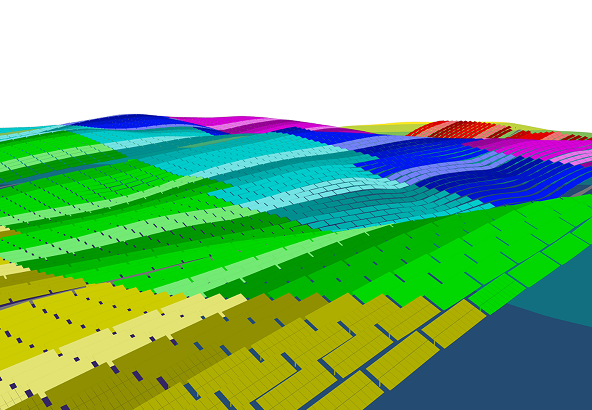
- High-resolution 3D terrain modeling
- Automated and terrain-following array placement
- Shading simulation across seasons and sun angles
- GCR and spacing optimization
- Integrated inverter and collection-system placement
Early-phase platforms such as PVFARM allow engineering teams to generate initial layouts with grading, terrain, and electrical context already embedded - giving downstream stakeholders earlier clarity into constraints, risks, and trade-offs.
Step 4: Electrical Design Integration
Once the physical layout is established, electrical design must be tightly integrated. Poor coordination between layout and electrical planning often results in excessive cable runs, higher losses, and inflated balance-of-system (EBoS) costs.
String Layout
String configuration should reinforce layout efficiency while maintaining electrical performance limits.
Key considerations include:
- Optimizing string routing to minimize DC cable length
- Strategic placement of combiner boxes
- Ensuring voltage drop remains within allowable limits
- Maintaining consistent string lengths to simplify maintenance
Inverter Station Placement
Inverter locations act as electrical anchors for each block and should be selected to balance DC and AC routing efficiency.
Primary placement objectives include:
- Minimizing DC cable distances
- Reducing trenching scope
- Providing safe and accessible O&M locations
- Maintaining required clearances and setbacks
- Balancing AC collection routing across the site
AC Collection System
The AC collection system ties the plant together and must be coordinated with civil and electrical layouts.
Key considerations include:
- Medium-voltage routing paths
- Trench depth and soil thermal properties
- Substation location
- Grid interconnection point constraints
Electrical Design Considerations
Final electrical checks ensure the system operates safely, efficiently, and within design limits:
- DC:AC ratio optimization
- Voltage drop limits
- Cable ampacity and thermal derating
- Grounding and bonding strategy
- Lightning protection
- Inverter loading curves and clipping analysis
Step 5: Layout Optimization
With an initial layout in place, iterative optimization is used to improve performance and reduce cost. This step often delivers the greatest overall project value.
Energy Yield Optimization
Energy-focused refinements aim to capture more production without materially increasing cost.
Common techniques include:
- Inter-row shading mitigation
- Fine-tuning row spacing and tilt angles
- Refining backtracking strategies for trackers
- Optimizing bifacial gain through albedo modeling and row height
- Verifying seasonal shading behavior
Cost Optimization
Reducing EBoS costs often requires small but cumulative design adjustments.
Typical cost-reduction strategies include:
- Minimizing cable lengths and trenching
- Optimizing earthwork volumes
- Streamlining access-road placement
- Reducing tracker or pile counts where feasible
- Favoring terrain-following designs to limit grading
Constructability Review
Optimization must be grounded in construction reality.
Key constructability checks include:
- Pile-driving feasibility
- Cut-and-fill balance and grading volumes
- Equipment access routes
- Laydown and staging areas
- Construction sequencing considerations
Pre-construction design tools such as PVFARM provide early visibility into grading volumes, energy-yield impacts, and cost-driving constraints - helping teams understand execution implications long before construction begins.
Iterative Optimization Process
Effective optimization is rarely linear.
Typical workflow:
- Evaluate multiple layout scenarios
- Perform sensitivity analysis on GCR, tilt, and spacing
- Compare energy yield against cost impact
- Select the configuration that delivers the best LCOE
Step 6: Layout Validation and Analysis
Before finalizing the design, the layout must be validated through simulation, engineering checks, and constructability review.
Energy Yield Simulation
Energy yield validation is a critical step before finalizing a utility-scale solar PV layout. Industry-standard tools such as PVsyst are commonly used to produce bankable energy studies and validate key performance assumptions, including:
- Annual Energy Production (AEP)
- Shading losses
- Soiling assumptions
- Degradation over time
- Performance ratio
Design platforms such as PVFARM are purpose-built to complement this process. By integrating layout, civil, and electrical engineering within a single environment, PVFARM provides instant, in-app energy insight during layout development - allowing teams to understand how design changes affect yield before committing to full bankable simulations.
Financial Analysis
Validated layouts feed directly into financial modeling.
Key metrics include:
- Levelized Cost of Energy (LCOE)
- Internal Rate of Return (IRR) and Net Present Value (NPV)
- Capacity factor
- Installed cost per watt
Technical Validation
Engineering checks ensure the design remains compliant and buildable:
- String sizing verification
- Voltage and current limits
- Cable sizing validation
- Inverter loading checks
- Compliance with applicable codes and standards
Constructability Review
Final constructability confirmation includes:
- Grading volume assessment
- Access and logistics evaluation
- Environmental mitigation planning
Step 7: Final Layout Documentation
The final stage translates the optimized design into formal documentation suitable for permitting, procurement, and construction.
Layout Drawings
Typical deliverables include:
- Site plan with final PV layout
- Electrical single-line diagrams
- Grading and drainage plans
- Access-road layouts
- Fencing and security designs
Technical Specifications
Supporting technical documentation includes:
- Module, tracker, and inverter specifications
- Design assumptions and criteria
- Energy yield reports
- Bill of Materials (BoM)
Deliverables for Permitting
Permit-ready packages often require:
- Environmental documentation
- Interconnection drawings
- Approved site plans
- Construction-ready drawings
Common Solar PV Layout Design Challenges and Solutions
Solar PV layout design often meets obstacles long before construction begins. From terrain limitations to environmental constraints, these challenges require thoughtful engineering solutions.
Below are the most common issues and the strategies used to address them:
- Irregular Site Boundaries: Use custom row lengths, flexible block sizing, and strategic segmentation to maximize usable land without compromising array performance.
- Steep or Variable Terrain: Apply terrain-following layouts, targeted grading only where necessary, and select tracker types suited to slope and contour variations.
- Shading from Trees, Terrain, or Structures: Adjust setback distances, conduct detailed shading analyses, and reorient arrays to maintain optimal irradiance and reduce shading losses.
- Limited Grid Capacity: Optimize the DC:AC ratio, evaluate the integration of energy storage, and consider phased build-out strategies aligned with grid upgrade timelines.
- Environmental or Regulatory Constraints: Map exclusion zones (wetlands, wildlife habitats, buffers) and adapt array placement to meet environmental and permitting requirements.
- High Grading or Earthwork Costs: Use terrain-following optimization to minimize earthworks and adjust pile lengths or foundation types to accommodate natural slopes.
- Long DC or AC Cable Runs: Optimize inverter placement, select appropriate voltage levels, and reconfigure array blocks to shorten cable routes and reduce electrical losses.
Best Practices for Solar PV Layout Design
Designing an efficient, buildable, and financially viable solar PV layout requires more than placing rows of PV modules on a map. Utility-scale solar projects succeed when developers and engineers follow a disciplined, data-driven process that balances energy yield, construction feasibility, regulatory constraints, and long-term operations.
The following best practices highlight the principles that advanced solar tracker design software tools, such as PVFARM help streamline by revealing constraints earlier, supporting smarter decisions, and accelerating iteration.
- Begin with comprehensive site data and surveys
- Use specialized layout tools for complex terrain
- Optimize for both yield and cost, not just one
- Consider construction feasibility from the start
- Coordinate across civil, electrical, and environmental teams
- Validate assumptions with high-fidelity energy modeling
- Maintain flexibility for multiple iterations
- Document design decisions rigorously
- Engage O&M teams early to reduce long-term issues
Designing Utility-Scale Solar With Precision and Confidence
Effective solar PV layout design is foundational to successful utility-scale solar projects. A systematic approach, supported by accurate data, robust engineering practices, and advanced layout tools, enables teams to maximize energy, minimize cost, and improve construction feasibility.
Upstream Design Decisions That Shape Downstream Execution
In utility-scale projects, early layout decisions carry downstream consequences across civil works, electrical design, construction sequencing, and project economics. This is where upstream solar site design software such as PVFARM plays a critical role. Rather than producing disposable prospecting outputs, it enables engineering and development teams to explore layout scenarios with construction-level constraints already embedded; including terrain, pile lengths, tracker geometry, grading limits, and electrical topology.
From Early Design Insight to Bankable Energy Studies
By integrating civil, electrical, and layout considerations at the earliest stages, teams gain faster visibility into trade-offs that would otherwise surface much later in design or during construction. This early-stage approach allows project managers and downstream stakeholders to work from layouts that are already aligned with buildable reality; thus reducing late-stage redesigns, improving cost certainty, and supporting smoother execution without changing how day-to-day project management is run.
Connect With Us Today
Optimized layout design is one of the highest-impact drivers of utility-scale solar performance, and with the right tools, teams can deliver more accurate designs, stronger cost control, and greater confidence from the outset.
To learn how PVFARM supports high-precision solar site design, request a demo or speak with our team today.
.jpg)

.jpg)
.png)

.png)